E-mail:
info@zhongdongcable.com
Tel.: +86 198 2988 5532

In wind and solar power projects, 35kV has established itself as the de facto standard voltage level for collector lines. But specifying that on a drawing is one thing—actually selecting the right cable, from conductor material to insulation type, from armouring structure to flame retardant rating, is a decision that directly affects project safety and economics over the entire lifecycle. This guide walks through the selection logic for 35kV medium voltage cables, grounded in real-world project conditions.
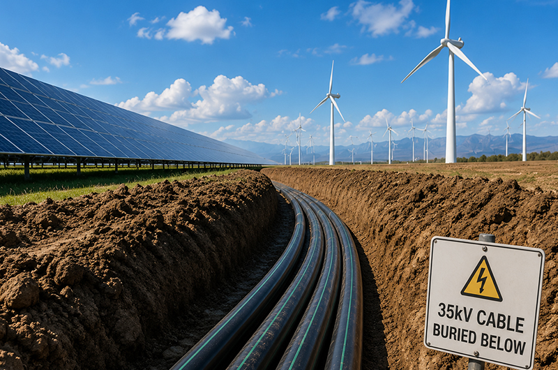
Why 35kV Became the Go-To for New Energy Projects
The electrical topology of a typical onshore wind farm or large-scale solar PV plant follows a consistent path: the generator or array output (690V or 10kV) first passes through a local step-up transformer to reach 35kV, then travels via collector lines to the main step-up substation, where it is boosted again for grid connection.
Three objective factors explain why 35kV has become the mainstream choice for new energy projects in China, Central Asia, Southeast Asia, and other emerging markets.
First, the transmission distance fits. The economic transmission radius for 35kV systems is roughly 5 to 15 kilometres—a good match for the footprint of most onshore wind farms. Beyond 15 kilometres, line losses rise noticeably, and only then does 66kV or a higher voltage become worth considering.
Second, the equipment supply chain is mature. 35kV switchgear, pad-mounted transformers, cable joints, and terminations are all highly standardized across both domestic and international supply chains. Lead times are short, spare parts are widely available, and field crews are already familiar with the equipment—an often-overlooked cost advantage in itself.
Third, the transmission efficiency advantage over 10kV is substantial—3.5 times greater. At the same current, a 35kV line delivers 3.5 times the power of a 10kV line (P = √3 × U × I). In practical terms: delivering the same power, a 35kV circuit draws only 28.6% of the current required by a 10kV circuit, and line losses (which scale with the square of current) drop to roughly 8% of the 10kV level. Compared with 66kV, switchgear and transformer costs typically run about 40% higher, and the technical demands on operations and maintenance crews are greater—not a cost-effective trade-off for sub-100MW projects.
For the vast majority of onshore wind or utility-scale solar projects under 100MW, 35kV represents the sweet spot balancing equipment cost, construction complexity, and operational losses.
Five Selection Dimensions: Breaking It Down Layer by Layer
Selection is not about copying a specification sheet. Below, working from the conductor outward, we examine the logic for each functional layer.
1. Conductor Material: Copper vs. Aluminium
This is the first decision point in any new energy project.
Copper has a conductivity of approximately 58 MS/m, compared with approximately 35 MS/m for aluminium. At the same cross-section, a copper-core cable delivers higher current-carrying capacity and lower DC resistance. Copper also outperforms aluminium in creep resistance and corrosion resistance—meaning that under high temperatures or daily load cycling, copper connections are less prone to loosening and more stable over the long term.
Copper is the better fit for higher voltage levels (≥35kV), heavier loads, and main circuits where reliability is paramount. Aluminium offers lower material cost and lighter weight, making it more economical for large-cross-section, long-distance transmission—but it requires proper copper-aluminium transition terminals and strict torque control during installation.
Take, for example, a 3×150mm² copper conductor specified under IEC 60502-2:2014. The standard sets a maximum DC resistance of 0.124Ω/km at 20°C. In actual factory test reports from a wind farm project in Uzbekistan, the measured values for the red, yellow, and green phases were 0.120, 0.121, and 0.120Ω/km respectively—a margin of approximately 3.2% below the standard limit.
For EPC buyers, requiring the supplier to report measured DC resistance per phase on the factory test certificate is the most direct way to verify that the conductor cross-section has not been reduced and that material purity meets specifications.
2. Insulation: Why XLPE Became the Default Choice
For medium voltage cables, the insulation choice is essentially between cross-linked polyethylene (XLPE) and polyvinyl chloride (PVC), with EPR (ethylene propylene rubber) appearing only in specialized flexible applications.
XLPE offers three key advantages.
Higher operating temperature. XLPE-insulated cables have a continuous operating temperature of 90°C and a short-circuit temperature rating of 250°C, compared with 70°C and 160°C for PVC. This higher thermal rating translates directly into roughly 15–20% greater current-carrying capacity for the same conductor cross-section.
Lower dielectric losses. XLPE has a dielectric constant of approximately 2.3, significantly lower than PVC's 4–5. At high voltages and over long distances, the difference in dielectric losses becomes substantial.
Higher insulation resistance. XLPE's volume resistivity is several orders of magnitude higher than PVC's, and its electrical properties degrade far less when exposed to moisture.
The critical performance indicator for XLPE insulation life is partial discharge (PD) level. Any voids or impurities within the insulation can generate minute discharges under high electric fields. Over time, these discharges cause electrical treeing and eventual breakdown. IEC 60502-2:2014 requires that partial discharge at 1.73U₀ does not exceed 10pC for medium voltage cables.
In the Uzbekistan project mentioned earlier, the three-phase PD values measured 4pC, 5pC, and 5pC—only 40–50% of the standard's maximum. Within the same standard framework, batch production with consistently low PD values (steadily below 5pC) is a strong indicator of stable cross-linking process control and high raw material purity.
3. Armouring: When It's Required and When It Can Be Omitted
Armouring serves one function: mechanical protection. Not every installation requires it.
Steel tape armour (designated by code "23" in IEC standards) is suitable for direct burial or installations where radial pressure may be a concern—backfill compaction, vehicle overrun risk, and the like. Steel wire armour (codes "33" or "43") is used where axial tension is a factor, such as vertical runs, submarine installations, or long-span crossings. For onshore new energy projects with direct-buried collector lines, steel tape armour is the standard fit.
Two parameters matter in steel tape selection: nominal thickness and lapping overlap ratio. IEC 60502-2:2014 specifies minimum steel tape thickness based on the cable's diameter over the armour bed. Buyers should request material certificates and actual thickness measurement records from the supplier. For projects in saline or high-humidity soils, standard galvanised steel may have insufficient corrosion margin—consider upgrading to a heavier zinc coating or adding an extruded PVC layer over the tape for composite protection.
Armouring can be omitted when the cable runs entirely within cable trays, conduits, or covered trenches where mechanical damage and rodent attack are not risks.
4. Sheath Material and Flame Retardant Rating: Match the Conditions, Don't Over-Spec
The sheath is the cable's last defence against environmental aggression.
PVC (polyvinyl chloride) sheathing is cost-effective, offers adequate resistance to acids, alkalis, and oils for typical outdoor applications, and provides some UV resistance—making it the most widely used sheath material for medium voltage cables. PE (polyethylene) sheathing provides better moisture resistance and low-temperature toughness, making it preferable for submerged or frozen-ground applications. LSZH (low-smoke zero-halogen) sheathing emits no toxic halogens when burned, making it mandatory for tunnels, indoor installations, and occupied areas.
Flame retardant ratings follow the same principle—match the rating to the actual risk. FR-C (corresponding to GB/T 18380.33-36 or IEC 60332-3-24) is appropriate for open-area field stations where fire risk is real but fire spread is manageable. Class A or B ratings are for underground galleries or tunnels where multiple cables are densely installed. If the host country's fire codes require limits on combustion gas toxicity, LSZH sheathing becomes mandatory—typically adding about 30% to material cost compared with PVC.
5. Cross-Section and Current-Carrying Capacity: Three Correction Factors Often Overlooked
Sizing starts with calculating the maximum continuous operating current, then applying correction factors to the standard current rating tables. Three corrections are most frequently missed.
Ambient temperature. Standard current ratings are typically based on an ambient temperature of 25°C (air) or 15–20°C (soil). Where the actual site temperature deviates from the reference, correction is required per IEC 60287. In Central Asia, for example, summer ground temperatures can exceed 40°C—derating the cable by roughly 10–15%.
Multiple cables in parallel. When several cables are installed in the same trench, heat dissipation is impaired, requiring a grouping correction factor.
Soil thermal resistivity. Sandy or rocky backfill has higher thermal resistivity than clay, directly affecting heat dissipation from the cable.
A common sizing mistake in new energy projects: sizing at 25°C ambient during the design phase, while the actual operating environment is consistently warmer. The result is a cable running at or above its thermal limit throughout its life, accelerating insulation ageing. The correct approach is to require the supplier to provide a calculation sheet based on actual site parameters during the bidding phase—not simply quoting standard-condition ampacity tables.
For the Uzbekistan wind project referenced here, the selected cross-section was 3×150mm², matched to the 26/35kV voltage level. Under the site's ambient temperatures and installation conditions, the ampacity margin was sufficient to meet the load profile specified by the design institute.
Factory Testing: Three Checks No EPC Buyer Should Skip
The factory test report is the most direct evidence of cable quality. These three tests are mandatory—none can be omitted.
Conductor DC resistance. This verifies that actual cross-section and conductivity meet specifications. Each phase is measured at 20°C, and measured values must not exceed the limits in Table 2 of IEC 60502-2:2014 for the specified cross-section and material. If a supplier's test report omits this item, or includes it but never states the margin, buyers should be alert—conductor diameter reduction or the use of low-grade recycled copper/aluminium are common practices among lower-cost manufacturers.
Partial discharge test. This is a direct measure of insulation purity and process control. Test voltage is 1.73U₀, with 10pC as the acceptance limit. For 35kV grades, consistently measured PD values below 5pC indicate stable cross-linking and clean materials; wide batch-to-batch variation or values approaching the 10pC limit suggest inconsistent process control.
AC voltage withstand test. This is the final verification of overall insulation integrity. In standard factory tests, 35kV cables are subjected to 65kV AC for 30 minutes—no breakdown is the pass criterion. IEC 60502-2:2014 also specifies a 4U₀ for 4 hours withstand test in the type-test phase—this is conducted during product qualification, not on every drum.
Environmental Adaptations for Central Asia and the Middle East
New energy projects in Central Asia and the Middle East present several environmental challenges that differ sharply from those in China's eastern coastal plains. Three areas require special attention during selection.
Extreme temperature swings. Cyclical thermal expansion and contraction place stress on terminations and joints. Selection should include a review of the supplier's insulation shrinkage data and specific requirements for semiconductive layer stripping and stress cone installation. Some projects have already shifted to pre-molded cold-shrink terminations in place of traditional heat-shrink types to reduce the impact of installation quality variability on temperature adaptation.
Sand, dust, and UV exposure. PVC sheathing accelerates ageing under prolonged sunlight—surface cracking and plasticiser migration are the visible signs. For above-ground cable runs, specify sheath thickness at the upper end of the IEC tolerance, or add separate mechanical/UV protection.
Saline and alkaline soils. Some project sites in Central Asia have low pH soils (below 6), which are notably corrosive to steel tape armour. Corrosion rates in such soils can be two to three times those in neutral soils. Mitigation options include: specifying heavier galvanised coating (≥275g/m² per side), adding an extruded PE layer over the steel tape to create a composite sheath, or including a salt spray test requirement (e.g., 240 hours with no red rust) in the technical specification.
Closing
Selecting medium voltage cables is not a matter of pulling a model number from a catalogue. Copper or aluminium depends on load density and budget. XLPE for insulation is largely settled, but partial discharge levels are what separate good from average. Armouring—add it or not, and how much—depends on the mechanical risks along the cable route. Flame retardant rating follows the local fire code, not the highest available grade. And cross-section sizing must be based on the actual site environment, with correction factors applied—not on standard-condition ampacity tables.
Behind every well-performing 35kV collector line is a set of technical parameters that have been matched, item by item, to the specific conditions of the project.
The technical data and test results referenced in this article are derived from actual factory test reports (executed to IEC 60502-2:2014) for Zhongdong Cable Manufacturing Co., Ltd's supply to an onshore wind farm project in Uzbekistan. For assistance with medium voltage cable selection for new energy projects in Central Asia, the Middle East, or other regions, EPC contractors and engineering institutes are welcome to contact us for project-specific sizing calculations and historical test report copies.
Standard references in this article: IEC 60502-2:2014 Power cables with extruded insulation and their accessories for rated voltages from 1kV (Um=1.2kV) up to 30kV (Um=36kV) – Part 2: Cables for rated voltages from 6kV (Um=7.2kV) up to 30kV (Um=36kV)


 CU/XLPE/PVC Single Core Power Cable 0.6/1kV
Zhongdong Cable combines premium raw materials, large-scale manufacturing capabilities, and strict quality control systems to deliver cable products that fully match your technical requirements and brand identity.