E-mail:
info@zhongdongcable.com
Tel.: +86 198 2988 5532

When a project is delayed because a cable route is crowded, a termination does not fit, or a quotation excludes installation accessories, the choice between single-core vs multicore Low Voltage Cable matters. For anyone comparing the best low voltage cable for a three-phase motor or planning low voltage cable selection for industrial buildings, the decision affects conductor size, voltage drop, and installation cost—not just the cable price. Start with the load, route, environment, and applicable standards: ampacity, IEC 60228 conductor class, and IEC 60502-1 voltage rating are key specification terms.

A single-core cable contains one insulated conductor. A multicore cable brings two or more insulated conductors together under a shared outer sheath. In a three-phase installation, a common comparison is three separate single-core phase cables against one three-core cable; a neutral or protective conductor may be additional, depending on the circuit design.
The construction changes how the circuit is routed, supported, terminated, and cooled. Neither design is automatically safer or more efficient. The suitable option depends on current, conductor material and cross-sectional area, installation method, ambient temperature, grouping, and the manufacturer’s ratings.
Separate phase cables can be useful for large conductors, long routes, or layouts where individual cables need to be positioned in a trefoil or flat formation. They can also be easier to handle than one large, stiff multicore cable. However, separate cables require suitable cleats or supports, careful phase identification, and enough space for bends and terminations.
For AC circuits, arrange all phase conductors together as the design requires. Magnetic effects can arise when single-core AC cables pass individually through ferromagnetic steel plates, glands, or enclosures. The cable route and entry details must therefore be coordinated with the electrical design; nonmagnetic components or appropriately grouped conductors may be needed. Do not treat this as a minor accessory choice.
A multicore cable keeps the circuit conductors together, which can simplify routing and help protect them with a common outer sheath. It often suits building distribution, control circuits, and equipment connections where the route and termination space can accommodate the cable’s overall diameter and minimum bending radius.
There are trade-offs. A large multicore cable can be heavy and difficult to pull through restricted routes, while the shared construction may limit how conductors are rearranged at the destination. Its current-carrying capacity must be selected from the applicable cable data and installation conditions; do not assume that putting conductors together gives the same rating as separate cables.
The table gives a practical, general comparison. Exact ratings vary by cable design, conductor size, insulation, installation method, and local code, so the manufacturer’s datasheet and project calculations take precedence.
| Specification factor | Single-core low voltage cable | Multicore low voltage cable | What to check |
|---|---|---|---|
| Construction | One insulated conductor per cable | Two or more insulated conductors under a common sheath | Number of phases, neutral, and protective conductor requirements |
| Routing | Individual conductors can be arranged to suit the route | One cable route carries the grouped circuit conductors | Tray, conduit, trench, bends, pulling tension, and available space |
| Terminations | More individual cable ends, glands, and support points may be required | Fewer cable entries may be needed, but the cable may need more termination space | Enclosure entry, lug size, gland compatibility, and bend radius |
| Thermal rating | Depends on conductor arrangement, spacing, and installation conditions | Depends on the number of loaded cores and heat dissipation | Ambient temperature, grouping, installation method, and applicable derating factors |
| AC magnetic considerations | Phase conductors must be arranged and routed with magnetic effects in mind | Conductors are generally grouped within one cable construction | Enclosures, glands, supports, and cable formation |
| Typical selection | Large conductors, some plant connections, or routes needing separate cable placement | Many building circuits, equipment connections, and distribution routes | Load calculation, local regulations, and manufacturer guidance |
For both types, specify the rated voltage, conductor material, cross-sectional area, insulation and sheath materials, conductor class, number of cores, and any required fire, oil, UV, or water performance. IEC 60228 covers conductor classes and nominal cross-sectional areas; IEC 60502-1 addresses construction and testing for power cables with extruded insulation in its stated voltage range. Confirm that the selected product and project jurisdiction align with the relevant standard and edition.
Once the basic construction is clear, match it to the route and work sequence. A cable that looks economical on a schedule can become difficult to install if the pulling path, bending space, or termination cabinet was not considered.
For a three-phase motor feeder, compare the calculated load current and starting conditions with the cable’s permissible current rating and voltage-drop limits. A separate single-core arrangement may suit a design with large conductors and planned trefoil cleating. A multicore cable may be practical when the route, cable size, and motor terminal box allow it. Check the motor manufacturer’s terminal requirements and the project’s protection and earthing design before deciding.
For a building route with several circuits, a multicore cable can reduce the number of separate cable runs for a circuit and give installers a single sheath to identify and support. But cable trays can contain many grouped circuits, so the designer must assess the effect of grouping and temperature on ampacity. A tidy route does not remove the need for derating calculations.
On a long run, calculate voltage drop using the conductor resistance and reactance appropriate to the cable and installation. For a balanced three-phase circuit, a commonly used engineering form is ΔV ≈ √3 × I × L × (R cosφ + X sinφ), with units and conductor-temperature assumptions applied consistently. Single-phase circuits use a different expression. The project designer should verify the formula and limits required by the governing code.
In a tight cabinet or a route with small bends, compare the cable’s outside diameter, minimum bending radius, mass, and pulling requirements. A single-core arrangement may offer routing flexibility, while a large multicore cable may reduce the number of separate pulls but be harder to turn or land. Review the actual datasheet dimensions rather than relying on a general rule.
There is no universal rule that single-core or multicore cable costs less. A fair comparison uses the same conductor material, cross-sectional area, insulation, sheath, voltage rating, certification, and order length. Then add the costs that differ between installation methods.
Request like-for-like quotations and state whether the price includes test documents, packing, delivery, and accessories. Zhongdong Cable Co., Ltd. can be included in a supplier comparison by asking for a project-specific datasheet, construction details, applicable test documentation, and a quotation against the same technical schedule as other manufacturers. Verify each item against the project specification rather than assuming that a brand name alone establishes suitability.
Public, independently verified customer reviews are not provided here, so it would be misleading to invent quotations or claim a particular satisfaction score. In project feedback, the recurring practical concerns are usually more specific: whether the cable arrived with the agreed construction, whether its actual dimensions fit the route, whether documentation was available, and whether the terminations could be completed without rework.
Use those concerns as a procurement checklist. Ask for cable markings and datasheets before delivery, confirm reel lengths and outer diameters, and inspect the cable against the approved submittal. Ask installers to report pulling difficulty and termination time against the work plan. These records create useful project evidence without presenting unverified opinions as customer testimonials.
Consider a small manufacturing-site upgrade with a three-phase motor feeder, a crowded tray, and a compact motor terminal box. The design team first compares one multicore cable with three single-core phase cables, then checks the motor current, route length, voltage drop, tray grouping, bend radius, and termination space. The compact box favors a cable the installer can land without exceeding the specified bend radius; the crowded tray makes support spacing and cable arrangement equally important.
This is an illustrative engineering scenario, not a claim about a named customer or measured project result. Its lesson is practical: choose the cable after checking the route and terminations, then compare complete installed cost. A quotation that omits cleats, glands, or required documentation is not directly comparable to one that includes them.
For a quick, unbiased shortlist, rank the options against the actual design rather than using one universal winner:
Before releasing a purchase order, confirm the load and protection design, conductor size, voltage rating, installation method, environmental conditions, route length, cable arrangement, accessories, and required compliance documents. Ask the supplier to identify assumptions in the quotation and resolve deviations before manufacture.
Single-core low voltage cable is often a strong candidate when separate conductors suit the circuit layout and the project can manage the additional supports, terminations, and AC cable arrangement. Multicore low voltage cable is often a strong candidate when grouping the circuit conductors simplifies the route and its size, thermal rating, and termination needs fit the installation. Neither is suitable if its verified ratings or physical dimensions fail the design conditions.
For your next step, prepare a one-page schedule showing load current, system voltage, phase and core count, route length, installation method, environment, and applicable standards. Send the same schedule to Zhongdong Cable Co., Ltd. and other qualified suppliers, then compare datasheets and complete installed-cost quotations on equal terms. That process turns a single-core vs multicore low voltage cable debate into a traceable engineering decision based on ampacity, voltage drop, conductor construction, and the real installation route.


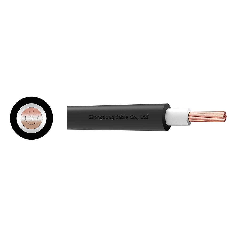 CU/XLPE/PVC Single Core Power Cable 0.6/1kV
Zhongdong Cable combines premium raw materials, large-scale manufacturing capabilities, and strict quality control systems to deliver cable products that fully match your technical requirements and brand identity.