E-mail:
info@zhongdongcable.com
Tel.: +86 198 2988 5532

To select Low Voltage Cable for industrial plants, start with the load and route, then verify ampacity, voltage drop, short-circuit withstand, and environmental suitability before ordering. This workflow for industrial power cable sizing covers cable ampacity calculation, motor feeders, and cable-tray installation; it also explains the professional checks known as derating factor, voltage drop, and short-circuit withstand. The result should be a documented cable specification—not a guess based only on conductor size.
Important about case studies: No sourceable, independently verifiable plant-user account was provided for this article. Rather than invent a customer story or claim a project result, the guidance below is tied to established engineering standards and asks readers to document their own project inputs and checks.

In IEC terminology, low voltage generally covers systems up to 1,000 V AC or 1,500 V DC. Confirm the project’s governing code and equipment ratings: regional rules, utility requirements, and the approved design basis take precedence over a generic guide. For many industrial power circuits, the cable voltage designation, such as U0/U, must be compatible with the system and earthing arrangement.
Collect the latest single-line diagram, load schedule, equipment data sheets, site temperature and routing details, and the applicable cable and installation standards. IEC 60364-5-52 addresses wiring-system selection and erection, IEC 60228 specifies conductor classes and resistance requirements, and IEC 60502-1 covers power cables with extruded insulation for rated voltages from 1 kV up to 3 kV. Check the current edition adopted by the jurisdiction rather than relying on an old project template.
Use manufacturer data for the selected product—not a generic table for a cable that only looks similar. Insulation type, conductor material, conductor class, number of loaded conductors, and installation method can change the allowable current and the applicable correction factors.
Tools: Single-line diagram, load schedule, equipment data sheets, and route drawing.
Action: Identify whether the circuit is a motor feeder, heater, lighting circuit, control supply, or another load. Record nominal voltage, phase arrangement, load current, power factor where relevant, duty, starting characteristics, route length, and the protective device. Separate continuous operating load from short-duration starting or transient conditions.
Parameters: Use the equipment manufacturer’s rated and starting data, the project’s design current, and the actual one-way route length. Record conductor material and the required cable voltage rating. Do not estimate missing values from a neighboring circuit.
Check: Confirm that the load, source, and protective device agree across the drawings and schedules. Check that the route length is measured along the cable path, not as a straight-line distance.
If it fails: Resolve inconsistent ratings or missing route details with the responsible electrical designer before sizing. Mark assumptions clearly and do not release a cable specification that depends on unapproved assumptions.
Tools: Site survey, cable specification, manufacturer datasheets, and area-classification documents where applicable.
Action: Select conductor material and class, insulation and sheath materials, number of cores, armour or other mechanical protection, and any required fire-performance characteristics. Check whether the cable will be exposed to oils, chemicals, moisture, UV, abrasion, vibration, or high ambient temperature. For variable-speed-drive circuits, follow the drive and motor manufacturers’ instructions for cable construction, screening, grounding, and installation.
Parameters: Match the cable’s voltage designation, temperature rating, conductor class, and environmental ratings to the equipment and route. Confirm fire and smoke requirements against the project specification and local regulations; do not infer them from a marketing description.
Check: Verify that the exact product datasheet covers the intended use and that glands, lugs, and terminations are compatible with the conductor and cable construction.
If it fails: Request a compliant product datasheet or select a construction rated for the actual exposure. If the route crosses different environments, assess each section and specify suitable protection or a transition detail.
Tools: Manufacturer ampacity tables, applicable code tables, installation drawings, and a calculation sheet.
Action: Select the base current-carrying capacity for the cable’s actual installation method, then apply the correction factors required by the governing standard and manufacturer. Common influences include ambient temperature, grouping with other loaded circuits, installation in thermal insulation, soil conditions for buried cables, and the number of loaded conductors.
Parameters: Use the table column that matches the conductor, insulation, cable construction, and installation method. Record every applied correction factor and its source. The corrected cable capacity must satisfy the applicable relationship between design current, protective-device rating, and cable capacity under the governing code.
Check: Confirm that the circuit-protection rules are met—not merely that the cable’s nominal ampacity exceeds the load current. Review manufacturer limits for terminals and equipment as well as the cable itself.
If it fails: Recheck the installation method and grouping assumptions. If the corrected capacity remains insufficient, consider a larger conductor, a different route or installation method, or an approved change to circuit design. Recalculate after any change.
Tools: Cable resistance and reactance data, route length, load current, power factor, and a calculation sheet.
Action: Calculate voltage drop using the method required by the applicable standard. For a balanced three-phase circuit, a commonly used form is ΔV = √3 × I × L × (R cosφ + X sinφ). For a single-phase circuit, the corresponding form commonly includes a factor of two: ΔV = 2 × I × L × (R cosφ + X sinφ). Use consistent units; if R and X are in ohms per unit length, L must use the matching length unit. Follow the governing standard’s method and definitions.
Parameters: Use resistance at the relevant conductor operating temperature when required, the cable’s reactance where applicable, the actual route length, design current, and power factor. Check both normal operation and any additional starting or operating condition required by the project.
Check: Compare calculated drop with the project limit and equipment requirements at the point of use. Include upstream voltage drop if the design method requires a total circuit check.
If it fails: Recheck units, route length, temperature assumptions, and whether the correct current and power factor were used. If the calculation is correct, evaluate a larger conductor, shorter route, revised circuit arrangement, or other engineering solution, then recheck ampacity and fault performance.
Tools: Fault-current study, protective-device curves and settings, cable data, and applicable short-circuit calculation method.
Action: Confirm that the cable can withstand the thermal effects of the prospective fault until the protective device clears it. A commonly used adiabatic relationship is S = I√t/k, where S is conductor cross-sectional area, I is fault current, t is clearing time, and k depends on conductor and insulation conditions as defined by the applicable standard.
Parameters: Use the fault current at the cable location, the relevant protective-device clearing time, and the correct k value and assumptions from the governing standard. Check both the phase conductors and protective conductor as required, and consider the device’s let-through characteristics where applicable.
Check: Verify that the protective device clears the fault within the permitted time and that the cable’s withstand is adequate for the calculated fault duty. Confirm coordination with upstream and downstream devices where required.
If it fails: Review the fault study and device settings with the protection engineer. Possible design changes include a different cable size or protective device, but any change must be checked for selectivity, disconnection time, and equipment compatibility.
Tools: Cable schedule, installation drawings, approved datasheet, termination instructions, and inspection checklist.
Action: Write a complete specification that identifies voltage rating, conductor material and class, core count and size, insulation and sheath, armour or screening, fire-performance requirements, and applicable standards. State installation method, route conditions, termination type, and identification requirements. Review cable-tray fill, bend radius, pulling tension, support, segregation, and gland selection against manufacturer instructions and project rules.
Parameters: Specify the exact approved construction and relevant acceptance documents. Keep the calculation revision linked to the cable schedule and purchase request so that a product substitution triggers a technical review.
Check: Compare the delivered cable’s markings and documentation with the approved specification. Before energization, verify terminations, earthing and bonding, mechanical condition, identification, and required test records under the project commissioning procedure.
If it fails: Quarantine an unapproved substitute or damaged cable and raise a technical query. Do not resolve a mismatch by assuming that a similar-looking cable has the same rating or installation properties.
Before approving a cable, confirm that the load and route inputs are traceable, the cable construction suits the site, corrected ampacity is adequate, voltage drop meets the design limit, and short-circuit withstand and protective-device coordination have been checked. Then verify terminations, installation constraints, and purchase documentation. Keep calculations with the cable schedule so changes to load, route, grouping, or product selection can be reviewed instead of silently carried forward.
For an industrial plant, the most reliable selection is the one supported by project-specific calculations, current standards, and the manufacturer’s data for the exact cable. If any input—especially fault current, installation method, or environmental exposure—is uncertain, resolve it with the responsible electrical engineer before procurement or installation. This is the practical basis for sound low voltage cable selection, dependable industrial power cable sizing, and defensible checks of cable ampacity calculation, derating factor, voltage drop, and short-circuit withstand.


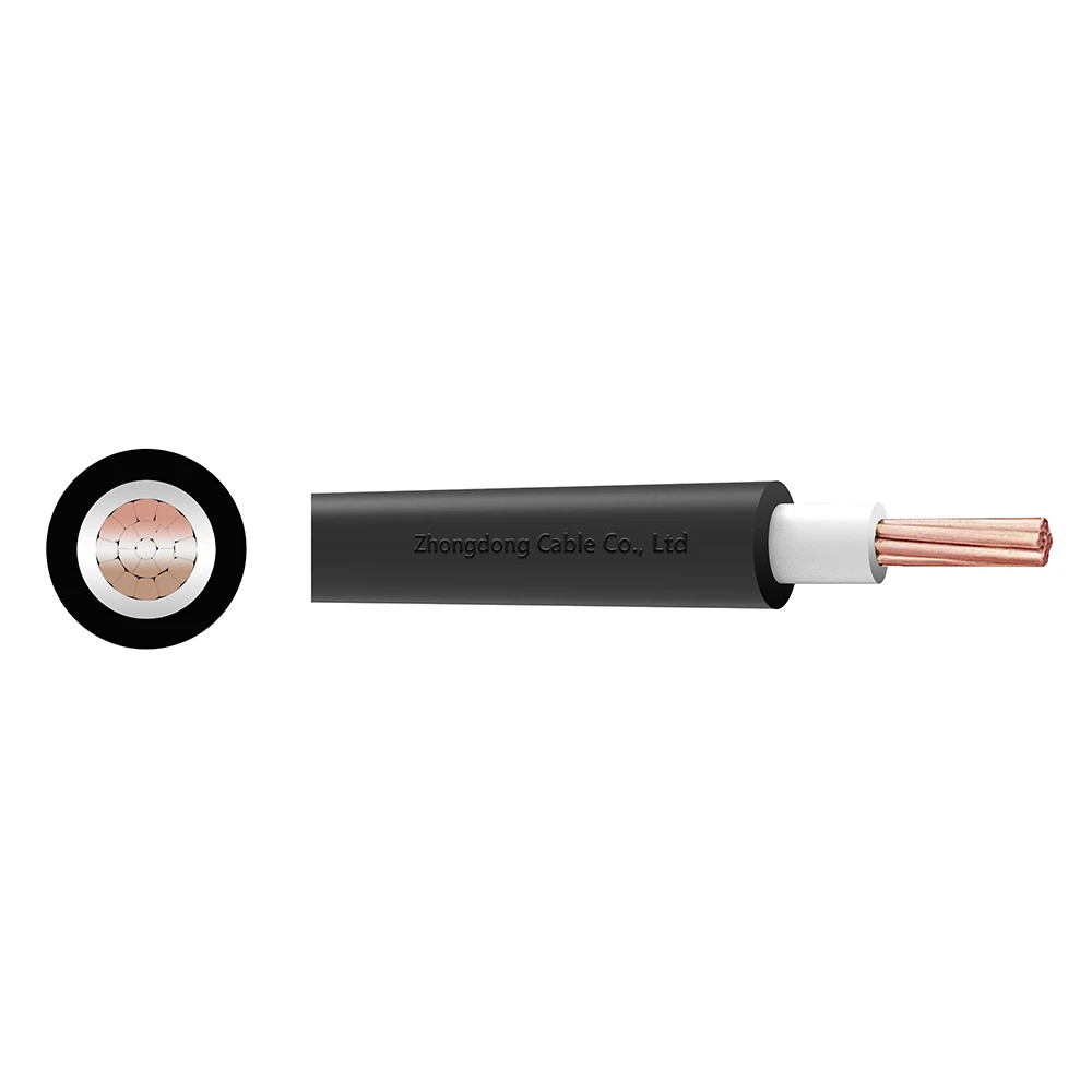 CU/XLPE/PVC Single Core Power Cable 0.6/1kV
Zhongdong Cable combines premium raw materials, large-scale manufacturing capabilities, and strict quality control systems to deliver cable products that fully match your technical requirements and brand identity.