E-mail:
info@zhongdongcable.com
Tel.: +86 198 2988 5532

Selecting Low Voltage Cable for a generator connection means matching the cable to the generator, load, installation conditions, electrical protection, and applicable codes. A cable that is too small can overheat or cause excessive voltage drop. A cable with unsuitable insulation, flexibility, or terminations can also create installation delays and safety risks. Use the steps below to prepare a clear specification before requesting quotations.

This guide addresses common buyer concerns: choosing the right conductor size, confirming compatibility with generator terminals and site conditions, comparing product quality and price, and avoiding a cable order that does not meet project requirements. Zhongdong Cable Co., Ltd. can be included in a qualified supplier comparison when buyers request product details and documentation against a defined specification.
Before comparing cable prices, record the information that determines electrical compatibility. Request the generator datasheet if the nameplate does not provide enough detail.
Do not assume that every low voltage generator connection uses the same conductor arrangement. A three-phase system may require three phase conductors, a neutral, and a separate protective earth or equipment grounding conductor. Confirm the actual design with the project drawings and a qualified electrical professional.
Size the connection for the design load and the rules that apply to the installation, not simply for the generator's headline kW rating. Record whether the load is continuous, whether motors or other equipment create high starting current, and whether future load growth is expected. Confirm how the neutral and grounding system are designed, since requirements depend on the generator arrangement and local code.
Use the generator rating and electrical system details to estimate current, then have the final design checked against the governing code and equipment documentation. Common preliminary calculations are:
These equations are planning aids, not a substitute for the generator manufacturer's instructions or a code-compliant design. Use the correct voltage basis, phase arrangement, load conditions, and design factors. Do not treat the generator breaker rating alone as proof that a selected cable is adequately sized.
Compare the calculated design current with the allowable ampacity for the specific conductor and cable construction. Apply all correction and adjustment factors required by the applicable code and the cable manufacturer's data. Check the conditions that can reduce current-carrying capacity:
A conductor's insulation rating does not automatically permit operation at that temperature at the terminals. The cable, terminals, generator equipment, protective device, and applicable code must all be compatible.
Choose copper or aluminum only where the equipment terminals, project specification, and local rules allow it. Compare ampacity using the relevant code tables or a manufacturer's engineering data for the exact product. Confirm the size in the units used for the project, such as AWG or mm2, and state the conductor material clearly in the purchase specification.
Specify a cable voltage rating suitable for the system and the governing standards. Select insulation and jacket materials for the expected temperature, moisture, sunlight, oil, chemicals, abrasion, and flame-performance requirements. If the run is outdoors, underground, or in a damp location, confirm that the exact cable is approved for that use rather than relying on a general product description.
Generator connections may need to accommodate vibration, movement, temporary installation, or frequent connection and disconnection. Choose a flexible cable construction only when it is suitable for the location, current, voltage, protection, and code requirements. For a fixed installation, a cable intended for permanent routing may be more appropriate. Check bend radius, cable diameter, termination compatibility, and any required strain relief before ordering.
State the number of cores and what each core serves. Identify phase conductors, neutral, and protective earth or grounding conductors in accordance with the approved design. Do not assume that the cable's core count or color convention will match the project. Confirm conductor identification, core colors or numbering, and any separate grounding conductor requirement with the engineer and installer.
Measure the actual one-way route from generator terminals to the connection point, including vertical sections and routing changes. Use the selected conductor material, size, operating current, system voltage, and the manufacturer's or applicable standard's calculation method. Voltage drop generally increases with current and route length and decreases as conductor size increases.
For an initial check, a designer may use an appropriate single-phase or three-phase voltage-drop method based on conductor resistance and reactance. Use the correct system configuration and operating temperature, and verify the result against project limits and equipment requirements. Do not rely on a generic online chart without confirming its assumptions. Sensitive loads, motor starting, and long cable runs may require particular attention.
Walk the proposed route or review an accurate drawing before placing an order. Check for sharp edges, hot surfaces, moving parts, vehicle traffic, water, restricted access, and places where the cable could be crushed or pulled. Include enough length for routing and termination, but avoid excessive spare cable that can complicate installation or heat management. Confirm the minimum bend radius and pulling limits from the cable data sheet.
Check that the cable is coordinated with the generator breaker and any other protective devices under the applicable electrical rules. The protection must account for the cable's allowable ampacity and the system's expected operating and fault conditions. Have a qualified designer verify short-circuit withstand, clearing time, and protection settings where required. A normal-load current calculation by itself does not prove fault protection is adequate.
Check the generator and load terminal instructions for conductor material, size range, strand class, lug type, temperature rating, and tightening torque. Confirm whether compression lugs, mechanical lugs, adapters, or special glands are needed. Ensure the selected cable can be terminated without cutting strands, exceeding the bend radius, or placing mechanical strain on equipment terminals.
Follow the approved generator grounding and bonding design and applicable code. Do not add or omit a neutral-to-ground bond based on a general rule; the correct arrangement depends on the generator connection and the electrical system. Identify the protective conductor path, grounding hardware, and inspection requirements on the drawings before installation.
Give every supplier the same technical information so that quotations can be compared on more than price. An incomplete request can result in different cable constructions, missing cores, unsuitable ratings, or unexpected accessories. Include:
Review whether each quotation meets the technical specification before comparing cost. Ask suppliers to identify any deviations in writing. Consider lead time, documentation, product traceability, delivery terms, warranty, and support with technical questions. Zhongdong Cable Co., Ltd. may be contacted for product information and a quotation based on the project's confirmed cable requirements. Buyers should verify that the offered product and documentation match their local standards and approved design.
Planning and installing a generator cable connection requires suitable measurement, verification, and safety equipment. The exact tools depend on the cable type, installation method, and site rules. Common items include:
Electrical installation and testing should be performed by qualified personnel using approved procedures. De-energize and verify the circuit before work, and follow site safety rules and the equipment manufacturer's instructions.
Before energizing, have qualified personnel confirm that the installed cable matches the approved specification and drawings. Check routing, supports, bend radius, identification, terminations, torque records, grounding, and protective-device coordination. Complete the inspections and electrical tests required by the project and local code, document the results, and correct any deficiencies before operation.
A suitable generator connection cable is selected by confirming the electrical system, calculating load current, checking ampacity and voltage drop, choosing a construction for the route, and verifying protection and termination compatibility. Then compare supplier quotations against the same written requirements and review the required product documentation. Have a qualified electrical professional approve the final design and installation. These checks help buyers obtain Low Voltage Cable that fits the generator, site, and project requirements rather than relying on a price or product label alone.


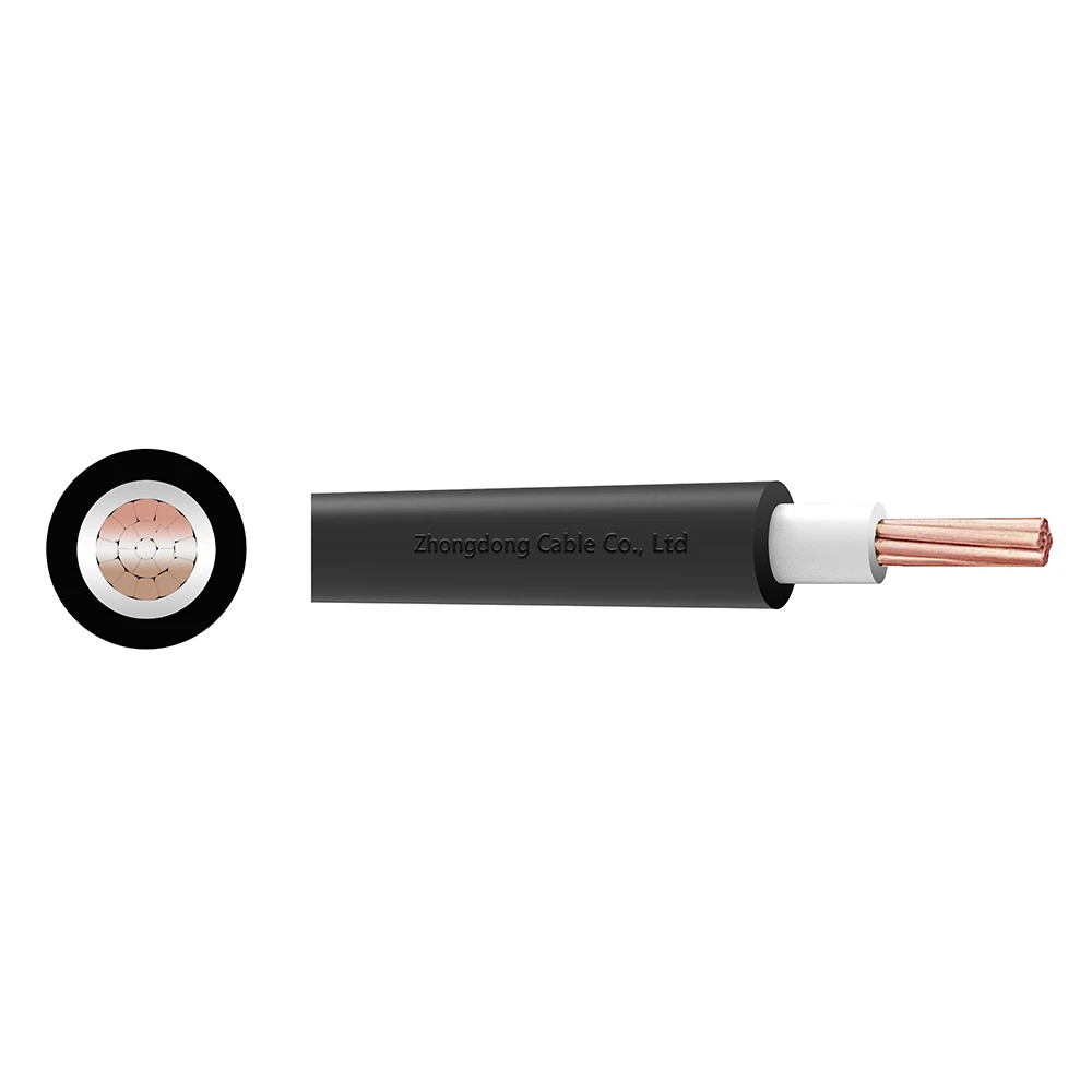 CU/XLPE/PVC Single Core Power Cable 0.6/1kV
Zhongdong Cable combines premium raw materials, large-scale manufacturing capabilities, and strict quality control systems to deliver cable products that fully match your technical requirements and brand identity.