E-mail:
info@zhongdongcable.com
Tel.: +86 198 2988 5532

With Zhongdong Cable Co., Ltd., you can calculate voltage drop in a Low Voltage Cable run, select a more suitable conductor size, and check the voltage available at the load. I’ll walk through the required inputs, the correct formulas, a worked 24 V example, and the checks that help prevent dim lights, motor starting problems, equipment faults, and wasted energy.
Voltage drop is the reduction in voltage between the power source and the load caused by the cable’s electrical impedance. A long run, high current, small conductor, elevated conductor temperature, or poor connection can increase the drop.
The practical result is a lower load-end voltage. Lighting may become dim, control equipment may behave erratically, and motors may draw more current or struggle to start. For businesses, selecting the cable based only on ampacity can therefore lead to operating issues, rework, and avoidable downtime.
Voltage-drop limits depend on the applicable electrical code, project specification, and equipment requirements. Treat the percentage targets in this article as design checks, not universal legal limits. Confirm the required limit for your installation before ordering a Low Voltage Cable.
I start by recording the following information. Accurate inputs make the result useful; guessing cable length or load current can produce a misleading conductor size.
For a two-wire DC or single-phase circuit, the outgoing and return conductors both contribute to resistance. If the route length is 30 m one way, the current travels through approximately 60 m of conductor. The formula below accounts for this with a factor of 2.
For a copper or aluminum two-wire circuit, a practical resistance-based calculation is:
ΔV = (2 × ρ × L × I) ÷ A
For a preliminary calculation at 20°C, common resistivity values are approximately 0.01724 Ω·mm²/m for copper and 0.0282 Ω·mm²/m for aluminum. Use the cable manufacturer’s resistance data for final design where available. Conductor resistance rises as temperature rises, so a 20°C estimate may understate the drop during operation.
Convert the result to a percentage with: Voltage-drop percentage = (ΔV ÷ source voltage) × 100. The estimated load-end voltage is: source voltage − ΔV.
For AC circuits, cable reactance and load power factor can also affect the result. A common three-phase calculation using conductor resistance and reactance per unit length is:
ΔV = √3 × I × L × (R cosφ + X sinφ)
Here, R and X are in Ω per unit length, L uses the matching length unit, and φ is the load power-factor angle. For a single-phase AC circuit, the corresponding approximation is ΔV = 2 × I × L × (R cosφ + X sinφ). Use consistent units and manufacturer data for R and X at the expected operating temperature. For preliminary sizing, a resistance-only method may be adequate in some cases, but confirm whether the project requires a full AC impedance calculation.
Suppose a machine has a 24 V DC supply, draws 20 A, and is located 30 m from the source. The circuit uses a copper Low Voltage Cable, so the outgoing and return paths total 60 m.
A 14.4% drop is too high for many 24 V applications. It may put the equipment below its permitted input-voltage range. This shows why a cable can meet an ampacity requirement and still be unsuitable for a long low-voltage run.
If the design target is 3%, the maximum permitted drop is 24 × 0.03 = 0.72 V. Rearranging the formula gives a minimum calculated area of approximately 28.7 mm² at 20°C. A standard 35 mm² conductor gives an estimated drop of 0.59 V, or 2.46%, at 20°C. At a conductor temperature of about 70°C, copper resistance is roughly 20% higher than at 20°C, so the estimate rises to about 0.71 V, or 2.95%.
This is an illustrative calculation, not a final cable approval. Check actual maximum conductor resistance, operating temperature, installation conditions, protective-device coordination, terminal capacity, and the equipment’s minimum voltage requirement before choosing a cable.
| Example check | 6 mm² copper | 35 mm² copper |
|---|---|---|
| Estimated drop at 20°C | 3.45 V | 0.59 V |
| Drop as a percentage of 24 V | 14.4% | 2.46% |
| Estimated load-end voltage at 20°C | 20.55 V | 23.41 V |
Use the design current rather than a typical average if the load can operate at a higher current. Measure the installed route, including rises, drops, and detours. For a circuit with multiple loads, identify where current changes along the route; a single-load formula may not represent a distributed-load circuit.
Multiply the system voltage by the project’s permitted drop percentage. For a 48 V system with a 3% target, for example, the maximum drop is 1.44 V. Confirm the target against local rules, contract documents, and equipment data rather than assuming one percentage applies to every circuit.
For DC or a resistance-based single-phase estimate, rearrange the formula:
A = (2 × ρ × L × I) ÷ ΔVmax
Then choose an available conductor size at or above the calculated value and recalculate using that actual size. For AC or three-phase systems, use the applicable impedance formula and consistent units.
A suitable Low Voltage Cable must also satisfy ampacity, installation-method derating, short-circuit withstand, insulation voltage and temperature rating, mechanical protection, and local code requirements. Check voltage drop and ampacity as separate design conditions; passing one does not guarantee passing the other.
Review the cable datasheet for conductor material, nominal cross-section, maximum conductor resistance, insulation type, and rated voltage. At installation, check for damaged insulation, loose terminations, incorrect polarity or phase connections, and undersized connectors. A high-resistance joint can create heating and additional voltage loss even when the cable calculation is correct.
A spreadsheet or electrical-design calculator can speed up calculations and make it easy to compare conductor sizes. I recommend recording the inputs, formula, temperature assumption, cable datasheet resistance, and final result so another engineer can review the design.
For conductor and installation requirements, check the standards and regulations adopted for the project. IEC 60228 covers conductors of insulated cables, while IEC 60364-5-52 addresses selection and erection of wiring systems. ASTM B8 applies to concentric-lay-stranded copper conductors in its stated scope. These standards do not replace a project-specific voltage-drop calculation, and the applicable edition and national amendments should be confirmed.
When evaluating suppliers, request traceable test documentation for the exact product and production batch, including conductor resistance and the tests required by the purchase specification. A procurement checklist can call for documented 100% continuity testing where applicable, dimensional checks to the specified tolerance, and a response target such as 24 hours for technical clarifications. These are requirements to verify with the supplier, not assumptions about a particular product or company.
Correctly sizing a Low Voltage Cable helps deliver adequate voltage to equipment, reduce nuisance faults, and avoid replacing an undersized cable after installation. It also helps project teams balance material cost against energy loss and operating performance, especially on long DC runs used in controls, lighting, communications, and distributed power systems.
Zhongdong Cable Co., Ltd. is a point of contact for buyers comparing cable specifications and planning a Low Voltage Cable order. Before purchasing, share the system voltage, current, route length, conductor material, operating conditions, required standards, and load-end voltage requirement. Clear inputs make technical review and product selection more efficient.
To calculate voltage drop in your next Low Voltage Cable run, record the system type, current, one-way length, material, and operating conditions. Apply the matching formula, convert the result to a percentage, and confirm the load-end voltage. Then check ampacity, temperature derating, installation rules, cable datasheet values, and connection quality before finalizing the size.
Keep the calculation with the cable schedule and verify voltage at the load under operating conditions when commissioning. With these practical steps, Zhongdong Cable Co., Ltd. and your project team can discuss cable requirements using clear, measurable specifications rather than guesswork.


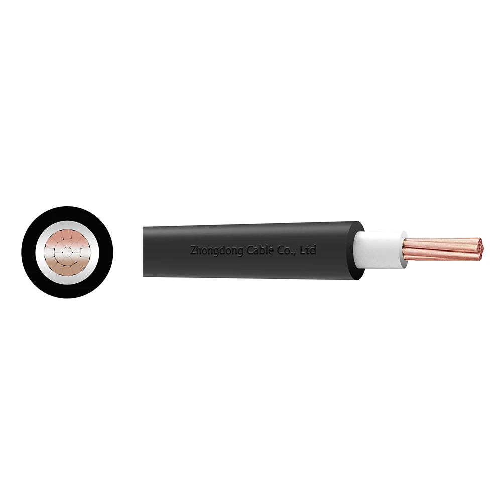
 CU/XLPE/PVC Single Core Power Cable 0.6/1kV
Zhongdong Cable combines premium raw materials, large-scale manufacturing capabilities, and strict quality control systems to deliver cable products that fully match your technical requirements and brand identity.