E-mail:
info@zhongdongcable.com
Tel.: +86 198 2988 5532

Choosing the right Low Voltage Cable size helps prevent excessive voltage drop, overheating, nuisance trips, and avoidable replacement costs. This guide explains the information to collect, the calculations to perform, and the checks to make before ordering cable. The selection must also comply with the electrical code and standards that apply at the installation site.
Readers comparing cable-sizing guides commonly need more than a formula: they need to know which inputs matter, how to check voltage drop, how installation conditions affect ampacity, and what details to give a supplier. Use the steps below as a planning guide, then have the final design checked by a qualified electrical professional.

Start with the equipment load and the supply arrangement. Cable size depends on current, system voltage, phase configuration, cable length, conductor material, insulation, and how the cable will be installed. A size that works for a short run in free air may not work for a long run in a warm conduit with several other loaded cables.
Load current is what the equipment draws in normal operation. Ampacity is the current a cable can carry under specified conditions without exceeding its permitted temperature. Published ampacity tables assume particular installation and environmental conditions. Apply the correction factors required by the relevant standard before deciding whether a candidate cable is suitable.
Collect reliable inputs before calculating. Missing route length, installation details, or supply information can make a precise-looking result unsafe or misleading. Use current manufacturer data and the applicable local wiring rules rather than relying on a generic online chart alone.
Write down whether cable length is one-way or total circuit length, whether resistance is stated per kilometer or per 1,000 feet, and whether the load value is in watts, kilowatts, or amperes. Keep units consistent throughout the calculation. For voltage-drop formulas, use resistance and reactance values at an appropriate conductor operating temperature when available.
Use the equipment nameplate or manufacturer instructions when they specify the design current. If current must be calculated from power, use the correct formula for the circuit and include efficiency and power factor where applicable.
In these formulas, I is current in amperes, P is power in watts, and V is the applicable supply voltage. Do not add an efficiency factor if the stated power and manufacturer data already account for it. For motors and other equipment with starting or inrush current, check the equipment and protective-device requirements separately.
Measure the actual one-way route, including vertical sections and routing around obstacles. Identify whether the circuit is DC, single-phase AC, or three-phase AC. The circuit type affects the voltage-drop calculation and the number of current-carrying conductors considered in ampacity tables.
Use an ampacity table that matches the conductor material, insulation, installation method, and temperature assumptions. Apply the correction or adjustment factors required for ambient temperature, cable grouping, soil thermal conditions, and other relevant site conditions. The corrected cable ampacity must satisfy the requirements of the applicable code and coordinate correctly with the load and protective device.
A simplified check is that corrected ampacity must not be less than the required design current. Many codes also require coordination with the protective-device rating and impose additional rules for continuous loads, motors, or special circuits. Follow the exact local requirements rather than treating this simplified check as a complete design rule.
Calculate voltage drop for the preliminary size using manufacturer resistance data or values permitted by the applicable standard. For a basic DC or single-phase calculation using conductor resistance R and one-way length L, the approximate voltage drop is 2 x I x L x R. For three-phase AC, a common approximation is sqrt(3) x I x L x (R x cos(phi) + X x sin(phi)), where X is cable reactance and phi is the load power-factor angle.
Use consistent units. If R and X are in ohms per kilometer, L must be in kilometers. If the data uses another length unit, convert it before calculating. The DC and single-phase approximation uses the outgoing and returning conductor path; the three-phase expression uses the stated three-phase relationship. For detailed designs, use the method, temperature assumptions, and cable data required by the relevant standard.
Convert the result to a percentage with: voltage-drop percentage = voltage drop / system voltage x 100. Compare it with the permitted limit for the circuit and the equipment. If the drop is too high, test the next larger cable size and repeat the ampacity and voltage-drop checks.
Check that the cable can withstand the expected fault current for the time taken by the protective device to disconnect. One commonly used adiabatic relationship is S >= I x sqrt(t) / k, where S is conductor cross-sectional area, I is fault current, t is disconnection time, and k depends on conductor material, insulation, and permitted temperature limits. Use the applicable standard and verified fault data; do not use this relationship as a substitute for protection coordination.
Also check termination temperature limits, mechanical protection, bending radius, burial depth, fire performance, and any requirements for neutral or protective-earth conductors. A cable that passes a current and voltage-drop calculation may still be unsuitable for the installation or the required certification.
Compare the candidate size against ampacity, voltage drop, short-circuit withstand, protective-device coordination, and installation requirements. If any check fails, move to the next suitable standard size and repeat the checks. Record the final assumptions and calculation results so the installer, reviewer, and supplier can confirm they are working from the same design.
A cable can carry the required current under a given installation condition and still produce excessive voltage drop because the route is long. Conversely, a cable that meets a voltage-drop target may not have sufficient corrected ampacity in a hot, grouped, enclosed, or buried installation. Both checks are necessary, along with fault and code checks.
A larger conductor usually costs more and may require larger terminals or conduit. However, reducing voltage drop can improve equipment performance and reduce resistive losses. Compare complete installed cost, operating conditions, expected service life, and any future load growth instead of choosing solely by the lowest quoted cable price.
Small errors in the input data can have significant consequences. Review each assumption before approving a design or requesting a quotation.
Get a qualified professional to review the design when the load is critical, the route is unusually long, the fault level is high, the site conditions are uncertain, or local regulations require formal engineering approval. A calculation guide cannot replace a site assessment or a code-compliant design.
Purchasing teams often need to compare offers that appear similar but differ in conductor material, construction, test evidence, or delivery scope. Provide a complete specification so each supplier quotes the same requirement and clearly identifies any exceptions.
Compare the offered cable datasheet with the approved design rather than relying on a product name alone. Confirm conductor material and size, core configuration, insulation and sheath, rated voltage, applicable standards, test documentation, and delivery details. Zhongdong Cable Co., Ltd. can be included in the supplier review process when requesting Low Voltage Cable information, quotations, and product documentation. Confirm that any proposed substitution is reviewed and approved by the responsible electrical designer before purchase.
Use this checklist to make the final review repeatable and to reduce misunderstandings between the designer, purchaser, supplier, and installer.
Correct Low Voltage Cable sizing brings together load current, installation conditions, voltage drop, protection, and compliance. Document the assumptions, verify the final selection against applicable standards, and confirm the delivered cable matches the approved specification before installation.


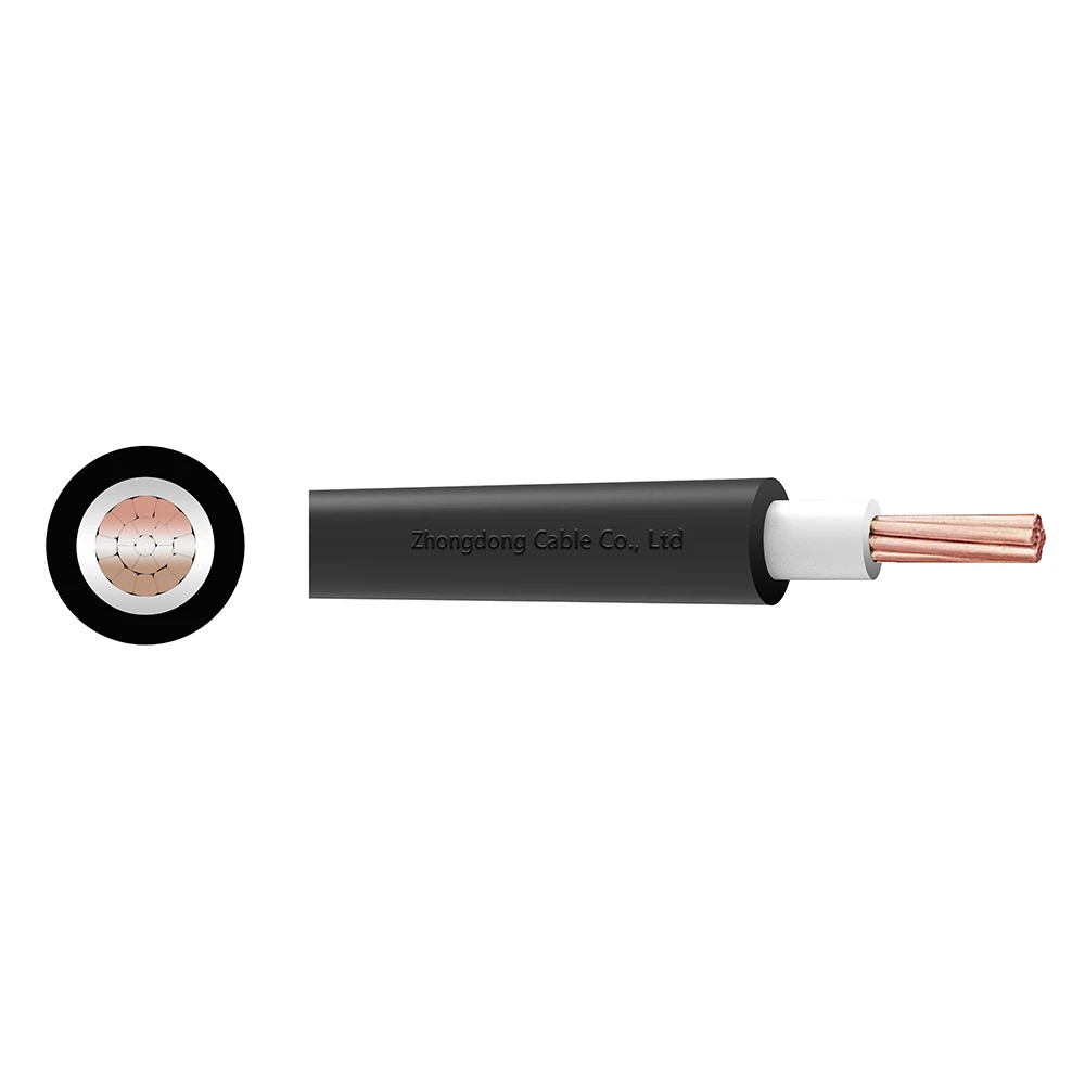 CU/XLPE/PVC Single Core Power Cable 0.6/1kV
Zhongdong Cable combines premium raw materials, large-scale manufacturing capabilities, and strict quality control systems to deliver cable products that fully match your technical requirements and brand identity.